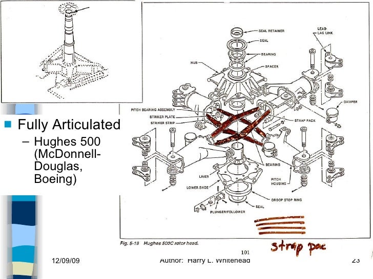
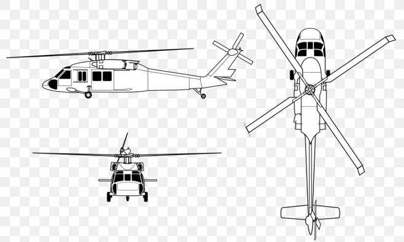
44 helicopter diagram with labels
Traditional Helicopter - Swashplate Setup — Copter documentation Below are the swashplate type selections using the H_SW_TYPE parameter. The diagrams shown label the servo attach positions as Servo 1, Servo 2 and Servo 3 for the three servo swashplate types. These also correspond to the default output functions for servo outputs 1 thru 3 on the autopilot for the servos used with these swashplate types. How Helicopters Work - HowStuffWorks Main rotor blade — The main rotor blade performs the same function as an airplane's wings, providing lift as the blades rotate — lift being one of the critical aerodynamic forces that keeps aircraft aloft. A pilot can affect lift by changing the rotor's revolutions per minute (rpm) or its angle of attack, which refers to the angle of the rotary wing in relation to the oncoming wind.
Helicopter Labels | Etsy Weaponized UH-60 Blackhawk Sticker Die Cut Decal - Self Adhesive Vinyl - Many Colors & Sizes - Customize - UH60 UH-60M US Army - #WL084. warlordone. (720) $8.99 FREE shipping. Helicopter Sticker For Car Window, Bumper, or Laptop. Free Shipping! VinylStickerStudio. (1,493) $3.99 FREE shipping.

Helicopter diagram with labels
Basic Flight Instruments Explained: The "Six Pack" - AviatorsHQ Those markings are labeled in the diagram below. Attitude Indicator Explained Heading Indicator (Gyroscopic System) This indicator is sometimes called the "Directional Gyro" or DG for short. This indicator basically tells you which way you are pointing, based on a 360 degree direction. anatomy of a helicopter . helicopter parts body icg ops 7th recovered. Uh huey 1d bell 3d helicopter turbosquid hq models. Apache ah 3d longbow animium categories. Chest human anatomy diagram body front thorax lungs heart bones cavity name ray thoracic parts sternum inside sucking contents wound. Helicopter Aviation This is sort of a complex diagram, but lets take it part by part. The blue line shows the motion of the rotor blade, moving forward due to rotation. The green line shows the relative wind. Since there is only a horizontal component to motion right now, the green line is horizontal. The pink line labeled tip plane path shows the orientation of ...
Helicopter diagram with labels. PDF 7 Vfr Aeronautical Chart Symbols - Tamu The limits of Class E airspace shall be shown by narrow vignettes or by the dashed magenta symbol. Individual units of designated airspace are not nec- essarily shown; instead, the aggre- gate lateral and verti- cal limits shall be defined by the follow- ing: Airspace beginning at the surface desig- nated around air- ports ... PDF VFR Chart Symbols - remotepilot101.com HELICOPTER ROUTE CHARTS - Aeronautical Information 28 AIRPORTS LANDPLANE All recognizable run-ways, including some which may be closed, are shown for visual identification. HELICOPTER ROUTE CHARTS HELIPORT SEAPLANE ULTRALIGHT FLIGHT PARK AIRPORT DATA GROUPING Boxed airport name indicates airport for which a Special Traf-fic Rule has been ... History of Flight Labeled Posters and Worksheets - Teach Starter A set of 4 posters and matching worksheets for aviation topics. This poster pack includes a set of labeled diagrams for: Airship Helicopter Airplane Hot air balloon You will also find matching worksheets included in this pack. Author Scott (Teach Starter) Teach Starter Publishing Helicopter cockpit presentation - IVAO - International Virtual Aviation ... The RPM gauge of a helicopter is a double functional instrument, the short needle marked with letter R and inner circle indicates main rotor RPM; the long needle marked with T and external circle indicates engine turbine RPM. Both have to be in the green area during flight.
Aircraft Cockpit Training Diagrams About the Diagrams All the cockpit diagrams are highly detailed and high resolution. wallpaper Heavy Quality Paper Diagrams are printed on either high quality 250gsm heavy duty paper (rolled posters), or 150gsm paper (folded posters). Posters can be printed on other substrates on request. cloud_download Digital Downloads The V-G Diagram (V-N Diagram) - Aviation Performance Solutions The V-G Diagram is a relatively unfamiliar diagram to most non-military pilots. However, it's full understanding and practical implication is absolutely critical to upset recovery and stall/spin training techniques. In the video clip below, Clarke "Otter" McNeace, discusses this diagram's value to a comprehensive upset recovery training ... Headset and Accessories - asa2fly.com Endorsement Labels NASA ASRS Forms Where to Buy ... Helicopter Adapter (HS-HEL-ADPT) $49.95. Quick view. Acoustic Foam Earseals (HS-1-SEALS) $10.95. Quick view. Headset Head Pad (HS-1-PAD) $19.95. Quick view. Microphone Muff (HS-1-MUFF) ... Helicopters - Jump! Inc. A picture diagram labels the parts of a helicopter, while a picture glossary reinforces new vocabulary. Children can learn more about helicopters online using our safe search engine that provides relevant, age-appropriate websites. Helicopters also features reading tips for teachers and parents, a table of contents, and an index.
Los helicópteros (Helicopters) - Jump! Inc. A picture diagram labels the parts of a helicopter, while a picture glossary reinforces new vocabulary. Children can learn more about helicopters online using our safe search engine that provides relevant, age-appropriate websites. Helicopters also features reading tips for teachers and parents, a table of contents, and an index. Helicopter Infographic Labeled Diagram R22 Helicopter Stock Vector ... Find Helicopter Infographic Labeled Diagram R22 Helicopter stock images in HD and millions of other royalty-free stock photos, illustrations and vectors in the Shutterstock collection. Thousands of new, high-quality pictures added every day. Blueprint Reading Basics - Redback Aviation The label for the 0.500 - diameter hole in Figure 3 must be at least 0.750 deep for parts to be properly assembled. Methods of Displaying Tolerances Tolerances may be displayed in three ways. You may see more than one method used in one print. Unless otherwise specified: One place decimals + / - 0.1 Two place decimals + / - 0.03 PDF Sample Helicopter Measurements - 2017 HELICOPTERS Sample Helicopter Measurements - 2017 C-01) The helicopter pictured here is only one possible configuration that satisfies rules. Total mass of helicopter excluding rubber motor is at least 2.5 g (3.e.) Rubber motor of any mass must be detachable from helicopter (3.i.) Helicopter labeled for easy identification (3.j.) Up to three ...
How A Quadcopter Works Along With Propellers And Motors The diagram is of a DJI Phantom 3 quadcopter, viewed from above with the rotors labeled 1 through 4. In this above diagram, you can see the quadcopter motor configuration, with the 2 / 4 motors are rotating counterclockwise (CCW motors) and the 1 / 3 motors are rotating clockwise (CW motors).
Airplane Diagram Pictures, Images and Stock Photos Browse 2,346 airplane diagram stock photos and images available, or search for paper airplane diagram to find more great stock photos and pictures. Newest results paper airplane diagram Airplane Plan. Black Outline Aircraft On White Airplane Plan. Black Outline Aircraft On White Background. EPS10 Vector Airplane on blue background.
Helicopter Controls - SpinningWing In accord with the diagram above, we let \(\Psi\) denote the azimuth angle of the blade within a rotor revolution. \(\Psi=0\) when a blade is over the tail of the helicopter, \(\Psi=90^o\) when the blade is to the right of the aircraft and \(\Psi=180^o\) when the blade is over the nose of the helicopter.
Technical Tips - Airbus Helicopters Canada Technical Tips. A couple operators have reported experiencing tail rotor pedal stiffness when hovering or in very low speed flight with a quartering tail-wind. The situation is relieved by pushing hard through the stiffness or increasing forward airspeed. Troubleshooting has revealed that the stiffness is caused by the radial clearance between ...
Helicopter Tail Rotors - Part 2 | AMU Magazine Figure 2 is the same assembly, except that now we are standing behind the helicopter looking directly forward at the tail rotor assembly. Figure 3: This picture shows how the pitch change mechanism moves the blades. Figure 4: The red and green arrows show how the slider slides left and right on the shaft.
PDF Airport Diagram Legend - FAASafety.gov U.S. Optical landing System (OLS) .OLS. location is shown because of height approximately 7 and proximity to edge of may erects an obslruttion fur types of airt:raft, Appmach light symbols are shown in the Flight Information Handbook. Airport diagram stoles are variable.
Helicopters by Bizzy Harris In Helicopters, beginning readers will learn about how helicopters help rescue people. Vibrant, full-color photos and carefully leveled text will engage young readers as they are introduced to the features that are unique to this rescue aircraft. A picture diagram labels the parts of a helicopter, while a picture glossary reinforces new vocabulary.
Airport Marking Aids and Signs - Federal Aviation Administration Helicopter Landing Areas. The markings illustrated in FIG 2-3-23 are used to identify the landing and takeoff area at a public use heliport and hospital heliport. The letter "H" in the markings is oriented to align with the intended direction of approach. FIG 2-3-23 also depicts the markings for a closed airport. Airport Signs
helicopter - Kids | Britannica Kids | Homework Help The diagram shows the different parts of a helicopter. Please enter a valid email address. To share with more than one person, separate addresses with a comma
How to Draw a Helicopter Easy Step by Step for kids - YouTube Hello Kids!Here I am showing you how to draw a helicopter. It's really very easy to draw helicopter. First you have to draw it's shape with the fan above it'...
Helicopter Aviation This is sort of a complex diagram, but lets take it part by part. The blue line shows the motion of the rotor blade, moving forward due to rotation. The green line shows the relative wind. Since there is only a horizontal component to motion right now, the green line is horizontal. The pink line labeled tip plane path shows the orientation of ...
anatomy of a helicopter . helicopter parts body icg ops 7th recovered. Uh huey 1d bell 3d helicopter turbosquid hq models. Apache ah 3d longbow animium categories. Chest human anatomy diagram body front thorax lungs heart bones cavity name ray thoracic parts sternum inside sucking contents wound.
Basic Flight Instruments Explained: The "Six Pack" - AviatorsHQ Those markings are labeled in the diagram below. Attitude Indicator Explained Heading Indicator (Gyroscopic System) This indicator is sometimes called the "Directional Gyro" or DG for short. This indicator basically tells you which way you are pointing, based on a 360 degree direction.


.jpg)
![Principles of Flight [Part 1] - Kereta Kancil Aku](https://blogger.googleusercontent.com/img/b/R29vZ2xl/AVvXsEhmb65BdArGIeGjpFuFGETLrc8u3bzLr4dncKg5W2AOq8lRZoVc1hvidyizX1xjzYKM8pBtrgi2KhfofX2NIMC-SSUYXR0Tk_HduD3WcJpYhUSzOrvY8kjK1bM-Ol3t6EPU_yX8pVUwpdU/s1600/helicopter-labeled-diagram[1].jpg)


Post a Comment for "44 helicopter diagram with labels"